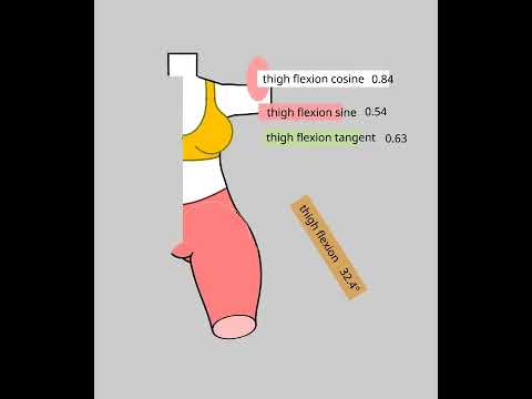
Rigged doll with "3D" foreshortening

In this new version of my rigged gym girl, I am converting everything to Synfig, taking advantage of Synfig features that aren’t possible in Inkscape:

  • partial line visibility with Width Point position
  • Using the MapRange Converter to modify the partial line visibility
  • nesting transforms for a “Faux 3D” in the leg

mujer articulada 03.sifz (30.4 KB)

Its still a work in progress. I need to redo it because I don’t work with the Skeleton foreshortening feature, and that’s important to get the knee, shank, foot, in the correct place. … and do all the limbs.

Thank you Rodolfo for making and correcting the MapRange function!!!

The previous version:

https://forums.synfig.org/t/gym-girl-rig-with-22-bones/17084/8

For some reason, the video is only visible in Firefox
Edit BobSynfig: Working fine on Brave and Chrome on Linux

Update: I corrected the thigh side and bottom visibility and continuity at high flexion angles.

Still need to work on negative abduction angles

Update Jul 21: negative abduction and thigh outline visibility corrected as much as possible.

5 Likes

I wanted to continue working on my project, but I got this error:

Is it just a matter of fixing something in the xml file?

At least the older version still works. Attached

mujer articulada 05.sifz (34.3 KB)

mujer articulada 04.sifz (33.3 KB)

At least my plan was to re-do some of this leg, because it needs to work with bones

update: ufff. I detected that the "animated…id=“right thigh flexion” block was moved a few lines under where it should be. Here’s the version 5 that works:

mujer articulada 05b.sif (729.0 KB)

This happened after I deleted one waypoint for “thigh flexion”, and unexpectedly all waypoints got deleted.

3 Likes

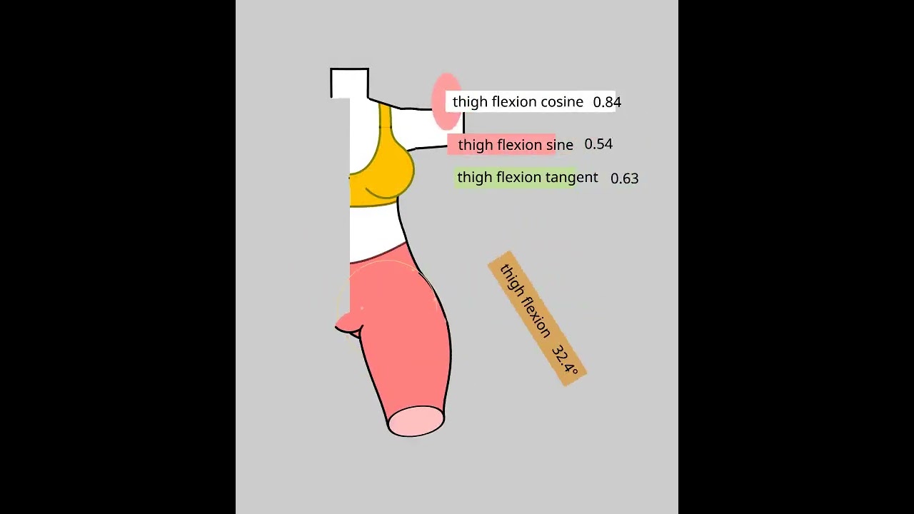
For future reference: this is how the end foreshortening is implemented.

fs=bone_local_length_scale

If the limb end is a ball, or a shape that should stay the same length as the limb foreshortens, I calculate the “anti-foreshortening”=afs=1/fs and apply it as the x or y scale that is parallel to the bone.

If the end is a flat surface, I calculate the “co-foreshortening”=cfs=sqrt(1-fs^2)/fs=sqrt(1/fs^2-1)=sqrt(afs^2-1) and apply it to the x or y scale of that group that will become the end cross section. This way, the end starts looking like a line when the limb is 100% length, but it appears 100% towards the viewer, when the limb is 0% length.

This “co-foreshortening” is also applicable to circles that wrap around the cylindrical (or conical) surface anywhere in the middle.

If the bone local length is greater than 1, then the flat end will continue to look like a line.
foreshortening 1.sifz (8.1 KB)

3 Likes

I created a valuenode named “Pythag_Compl_Prop”, which calculates the sqrt(1/x^2-1). I need this for perpendicular surface foreshortening. It’s based on the valuenode_angle and pow.cpp/h.

pythag_compl_prop demo.zip (7.9 KB)

Included sifz which only works with this new valuenode:

It works. It is still a work in progress. I don’t even know if the name should be “Pyhtag_Compl_Prop”

1 Like

Look at what they need to do to emulate this power

the rigging master (mistress?) tutorial that was referenced

manual section curve manipulation

2 Likes

Your formula can actually be built using several existing converters. However, it requires quite a lot of them. I ran into the same issue when I created the IK Bone setup using many converters, and the result was that Synfig became noticeably slower.

1 Like

Pin bones are actually possible in Synfig as well, but the functionality is quite limited. It may need something like SmartBone to make it more practical. Based on what I’ve seen in Moho, I’m not sure whether their implementation also relies on SmartBone as an additional component.

pin bone.sifz (5.5 KB)

2 Likes

Is “pin bone” what is needed so that the region above the joint doesn’t get stretched with the rest of the limb?

In the video I linked, it seems like the rigger is using 7 bones with non trivial connections, to obtain this result.

The way I did it is to make the top of the limb a nested group, and apply an “anti foreshortening” factor, so it remains un-stretched.

I created the new converter to make “Pythagorean complement foreshortening”

1 Like

As far as I know, pin bones don’t involve any stretching. The bones only translate and rotate, with each bone following the position of its corresponding pin.

To rotate a bone toward a target, you can use the Vector Angle and Subtract converters. You can refer to the example files for how they’re used. If you need the position of a bone that has a parent, you can use the Bone Link converter.

pin BONES new.sifz (3.9 KB) demo file donwload

Here’s a new pin bone setup I created, similar to the one shown in the first YouTube video.

1 Like

Thank you! I will try that. I am trying to find a way to make these bones creation more streamlined, because I will need many of them

1 Like

Hello Zainal,

I looked at the way that you keep the limb end shape constant, when the bone rotates and shortens. I see there’s a difference to how we apply the skeleton to the body parts:

Mine: all my limbs are a separate group, each with its own “Transformation” property. When I link the limb to the bone, the limb’s “Transformation” gets converted to a function of the bone status. This way the whole limb get’s stretched when the bone is stretched… even that end part that doesn’t need to be stretched. I mitigate this with the “anti-foreshortening method”.

Yours: the limbs are not grouped separately. The region vertices were converted to “Bone Link”. I have never seen that :smiley: I still don’t know how it works, but it may solve my problem with limb foreshortening.

I didn’t find documentation about Bone Links applied to Vertices… but I figured out how you do it. I also figured out that there are two skeletons:

“Pin bone” skeleton with bones Target, Knee, and Bone 24. This skeleton can be controlled directyl by the animator.

“Bone Bind” skeleton, with bones Bone 27 (thigh top),28 (thigh bottom),29 (shank top),30 (shank bottom). These bones should not be manipulated directly by the animator. It will mess the skeleton. It seems that there are functions that make these bones follow the bones in the “Pin Bone” skeleton, but maintain their length.

The limb vertices that must only rotate with the bone, should be linked to the correct Bone Bind bone.

The limb vertices that should stretch with the bone length, should be linked to a bone in the “Pin Bone” skeleton.

Yes, your approach is quite different. I’m still trying to understand how it is intended to be used as well, but I think it’s worth continuing to develop it and make it as practical and appealing as possible.

My approach started because I was challenged by a demo I saw in Moho. I spent quite a bit of time studying how the pin bone system works, then tried to recreate the same behavior in Synfig. After many experiments, I managed to get something similar working, although it’s still not perfect.

The Moho demo was in Chinese, so I couldn’t fully understand all the explanations, but it gave me enough insight to experiment and develop the idea further.

I am trying this way of linking outline vertices to bones, and making some “pin bones” (constant length bones).

I noticed that when a vertex is linked to a bone, I lose the ability to change “split tangents” to/from “merge tangents” by right clicking a node.

But I can still change node positions and tangents by dragging the ducks.

I need to temporarily unlink the vertex from the bone, to change the corner from smooth to cusp.

This is just a reminder for myself and anyone who wants to open the sifz, the MapRange converter feature is needed for the outlines to appear and erase at the appropriate times, and there’s this “Pull Request” that solved a bug to make it work 100% right.

There are instructions in that discussion above, to build it yourself. More reference below.

This is needed, until the next synfig release is released… to work with my character sifz.

I got a new reference and starting to try the bone linking with vertices.

segmented doll 5.sifz (23.6 KB)

1 Like

I avoided the problem of undesired foreshortening in the joints, by:

  • Making the joint a separate circle, layered under forearm and arm (this way its also simpler to maintain)
  • linking only the origin green points of the circle and outline, instead of the vertices

Does the torso lateral flexion look natural? :slight_smile:

Is there a way to push a button, and all the bone angles return to the initial state?

I still need to work with the knee angle logic

segmented doll 8.sifz (29.3 KB)

3 Likes

I am open sourcing them, because I want to see others make animations with it. Give credit if you use it.

Tell me if you make improvements.

Time to sleep :smiley:

I realized I don’t need to link vertices to bones, if I have the stuff I don’t want foreshortened, separate and only the origin linked to bones.

And I need to return to using groups, because that’s the only way I think I can morph it to 3/4 view and side view.

In this new version, only one line has the RangeMap feature: inner thigh section, so 1 line it may or may not work.

I didn’t use my new math converter. It wasn’t needed.

Foreshortening of arms only look nice up to 50% (shown below at 20%)

2 Likes

Thanks for this contribution

2 Likes

Update: now limbs and head are linked files, so they can be improved separately:

*make male torso

*make variations

*make different views

Get the files in my github

1 Like

Torso version 2.12 (in my github) is the last one, with only front view.

I will be working in side and 3/4 view. I am not sure if there will be a control joystick in the next version.

1 Like