Hi everyone! I’m Ahmed Fathy, a 3rd-year Computer Engineering student at Cairo University. I’m excited to be one of this year’s GSoC contributors and I’ll be using this thread to share updates throughout the summer.
Project Goal
The FFD layer lets artists warp artwork using an interactive 2D control grid — no skeleton rig needed. It’s ideal for squash-and-stretch, facial expressions, and cloth simulations.

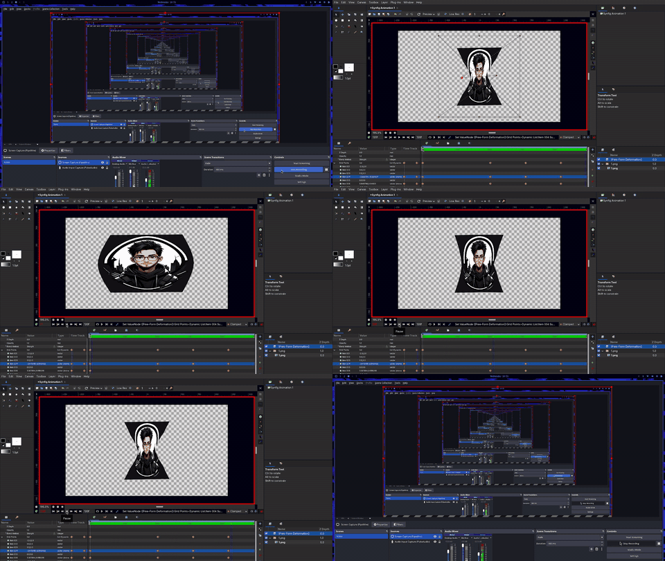
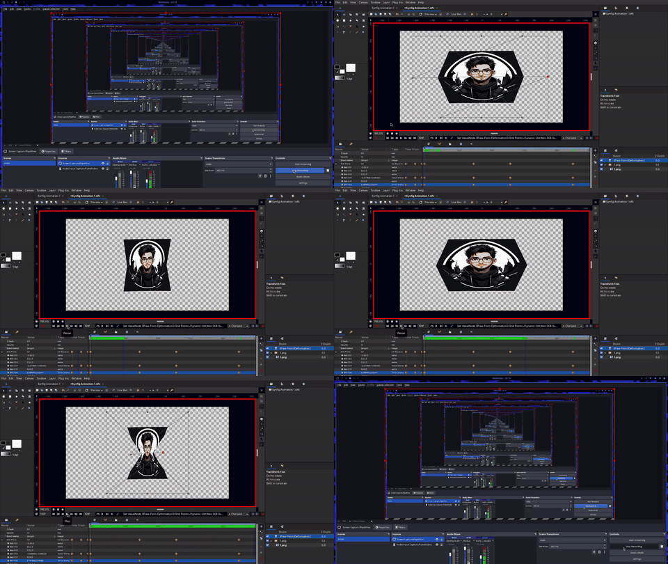
As part of my GSoC work on the FFD layer, I am preparing to upgrade the math engine from the initial bilinear interpolation implementation (from my MVP in PR #3724) to Catmull–Rom splines. To illustrate the difference between them, here is a GIF showing the comparison.
So, I need some feedback on this: do I need to remove the bilinear and just use the spline, or could I keep both and let the artist choose between them from a dropdown menu?
From a technical perspective, keeping both is entirely doable. Bilinear could theoretically be used for sharp folds (like paper or mechanical joints) or as a lightweight “draft mode” for better viewport performance, while Spline gives that smooth, rubbery C^1 continuity perfect for organic movement.
However, as a developer, I honestly don’t know what is actually best for the artists who use this app daily. I can build the math, but I don’t know artist’s workflows. I want to avoid cluttering the UI with a dropdown option if nobody is ever going to use the Bilinear mode, but I also don’t want to remove it if it opens up specific stylistic choices for them.
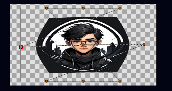
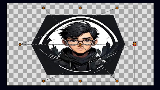
You can see that the spline tries to smooth everything, so I’m not sure if smoothing is really needed in all cases. For example, when we fold or crumple paper, we usually do not want smooth edges — we want them to stay sharp. I think Bilinear interpolation is better for that kind of deformation.
Excuse me, I don’t quite grasp the difference between the top and bottom. You mentioned it was for crumpling a face or something else. If you could show us your image with just the character and the decorative background removed, that might be clearer.
Otherwise, I think the other contributors might be able to tell us if there’s an equivalent function in the current layers?
To avoid duplication, I personally don’t know all the functions of Synfig Studio.
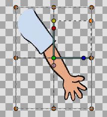
But otherwise, I think the ability to modify and stretch the desired element (a character or something else, an effect on text) within the grid clearly demonstrates its potential:
I hope you now see the difference (focus on the stretched corners).
I can make a roller option in a toolbox for the continuity (smoothness).
+
I think there is no duplication in the code, as that project was produced for a GSoC '26 project idea, but I will check for that.
Here is a summary of the progress and updates I’ve made on the FFD layer this week:
Tool & UI Additions
FFD Tool Implementation: Added the new Free-Form Deformation tool to the toolbox (state_ffd.cpp), which includes custom controls for adjusting grid subdivisions (X/Y) and smoothness.
Visual Grid Connections: Implemented visual grid lines that connect the control ducks directly in the workspace (duckmatic.cpp),but i had to make a new logic for connecting bezier.
Condition
What happens
is_ffd_grid == false
Old behavior preserved exactly — bezier chain drawn in sequence + loop closure. No change for Bline, polygon, etc.
is_ffd_grid == true
New 2D grid drawing — after all ducks are collected, iterate by row/col and draw horizontal + vertical connections forming a proper grid. The chain-of-beziers loop is skipped entirely.
UI & Icons: Registered and added custom vector icons for the FFD tool and layer. (Note: The current icon is a placeholder).
Grid Logic & Manipulation
Grid Point Interpolation: Added new interpolation logic. Now, when the grid subdivisions are modified (resizing the grid), the existing control points dynamically adjust to preserve the underlying shape.
Accurate Bounds Resolution: The grid now automatically calculates and fills the exact bounding box of the target image.
Undoable Controls & Reset: Added a “Reset Grid” button to the FFD tool options, allowing users to easily reset any manual adjustments to the grid points while safely supporting the undo history.
Layer Management & Validation
Automated Grouping & Validation: FFD creation is currently restricted to a single Switch layer, meaning it works perfectly with imported images (I am actively researching how to support shapes next). To prevent double-transformation misalignment, the action automatically encapsulates the Switch and FFD layers into a new PasteCanvas group and transfers the transformation properties cleanly to the parent.
Shape Layer Integration: Investigate how to make the FFD tool work seamlessly with shapes, handling the layer-level architectural differences between shape layers and image layers.
Custom FFD Points: Work on implementing custom FFD layer point behaviors.
Expanded Tool Options: Add additional configuration controls to the tool options panel.
Added a new Free-Form Deformation (FFD) Tool with support for both Uniform Grid and Custom Mesh deformation modes.
Implemented Delaunay Triangulation for automatic generation of non-overlapping custom mesh triangles from user-defined control points.
Now the shapes and images work well with FFD
Implemented inverse transformation mapping to correctly convert canvas coordinates into local layer space, for accurate mesh placement on transformed images.
Added native FFD wireframe rendering in Duckmatic, including support for both grid-based and custom triangulated meshes.
Enhanced mesh rendering stability by injecting image boundary corner points into triangulation, guaranteeing full image coverage and eliminating clipping-related issues.
Removed legacy FFD grouping logic from generic layer creation workflows and centralized it within the state_ffd file.
Updated layer menu behavior to launch the FFD workflow directly instead of creating incomplete FFD layers.
there was a problem on the toolbox undo does not reflect on the toolbox, another one was that the reset of the custom mesh was not implemented (both are fixed)
Mathematical & Rendering Improvements
Implemented robust Delaunay triangulation for custom mesh generation.
Added bounding-box corner injection to ensure complete texture coverage.
Applied inverse translation, rotation, skew, and scale transformations for accurate coordinate-space conversion.
Enforced counter-clockwise triangle orientation to maintain rendering consistency.
Eliminated dependency on clipping masks, preventing rendering artifacts and engine crashes.
finally i am working on making a good documentation for every thing i have implemented untill now.
Mesh Editing Capabilities: Allow users to click on an existing FFD layer to add, delete, or adjust the original source points without having to delete the layer and start over.
Bone System Integration: Enable linking FFD mesh points to Synfig’s Bone system, allowing the mesh to deform automatically when a skeletal bone is rotated or moved.
Performance Optimization (Caching): Cache the Delaunay triangulation data. The triangulation math should only run once when the mesh is created or edited, rather than recalculating every single frame during animation playback.
Visual Boundary Guides: Add an optional UI toggle to display a faint, dashed outline of the “invisible fence” and bounding box, so animators can visually see exactly where the deformation stops.
Soft Selection / Falloff: Introduce a “feathering” (tool option) or influence radius, where moving one point smoothly pulls neighboring points based on their distance, preventing sharp, jagged triangle edges during extreme warping.
Save/Load Polish: ensure the Custom Mesh data perfectly serializes/loads from .sifz project files.
Multiple Sub-Meshes: Allow the user to draw multiple disconnected custom meshes (e.g., one on the left eye, one on the right eye) inside a single FFD layer for better organization.
Hello, cordial greeting. Excellent work, all my admiration. In my humble opinion, as for your question, I think it would be redundant if the option was located there, why has it already been implemented to create squares or circles with splines. Besides, it would be a very good idea if custom mesh was also in the skeleton and bone creation options to design their influence. At the moment determining the influence of bones is very limited, they are two circles connected to each other forming a capsule, both in the skeleton layer and in the skeleton deformation layer. Another option would be to create a converter that transforms this custom mesh into bone influence
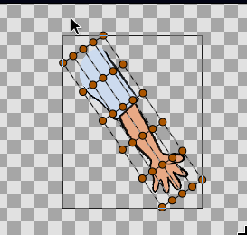
Live Interactive Preview: The tool now instantly draws the generated FFD mesh or grid bounding box over your image the moment you select it (before you click to click to create layer option in the toolbox).
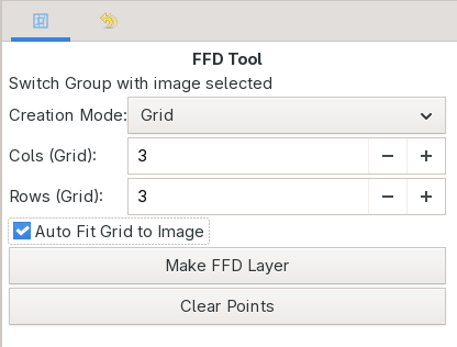
Fix Dynamic Grid Previews: Changing grid rows and columns in the tool options now instantly subdivides and draws the updated grid density live on the canvas.
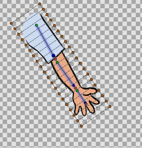
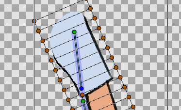
Auto-Fit Grid to Rotated Images: Upgraded the “Grid Mode” auto-fit to calculate an Oriented Bounding Box (OBB) instead of a simple axis-aligned box. If your target image is drawn at an angle, the auto-generated grid will seamlessly rotate to hug the image contours.
Its a checkbox option in the tool box you can use it or not.
Fix Strict Target Validation: The FFD tool UI now proactively disables itself and hides controls unless a valid Switch Group containing at least one image layer is selected, preventing the creation of broken, floating meshes.
Canvas Interaction Fixes: Fixed a bug where phantom mesh points could be placed during invalid tool states. Additionally, upon successfully creating a grid, the workspace now intelligently transitions directly to the Normal Tool so you can start deforming immediately.
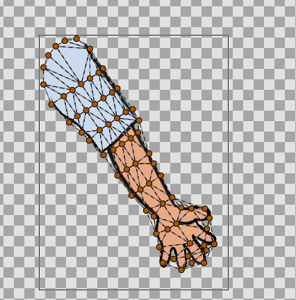
Intelligent Custom Mesh Auto-Fit: The Auto-Fit algorithm now fully supports “Custom Mesh” mode! It analyzes the target image’s alpha-channel, detects the boundary edges, and generates a perfectly contoured Delaunay-triangulated mesh that wraps the exact shape of your drawing.(you can try it now @zainal)
World-to-Local Space Coordinate Mapping: Implemented a real-time to_world and inverse transformation matrix system during the preview phase. This perfectly synchronizes the raw auto-fit mathematics (Local Space) with the canvas viewport (World Space).
Principal Component Analysis (PCA): Implemented a fast PCA math engine to dynamically calculate the eigenvector orientation and precise boundary limits of alpha-channel images for the new Oriented Bounding Box feature.
Alpha-Channel Edge Detection: Built a custom grid-sampling algorithm for the Custom Mesh mode that scans the image pixels, isolating high-contrast edge regions.
Transformation Stack Integration: Updated the Duckmatic system to properly push the current work area’s transformation stack into the FFD polygon ducks, fixing visual desyncs when editing points on transformed layers.
Architecture Cleanup: Centralized the complex Delaunay triangle culling logic into a core helper method, and refactored the duplicated mesh overlay rendering loop into a unified Duckmatic function for cleaner, safer code.
I haven’t forgotten about the feature to link the FFD mesh with the bone system! However, my priority right now is to ensure the core FFD tool is as stable and robust as possible first. I recently came across a video demonstrating a bone-mesh linkage, and I believe that’s the direction I’ll be taking (or something very similar) once the foundation is solid.
@zainal
First of all, thank you for taking the time to test the feature and leave such detailed feedback.
Regarding the first comment: yes, supporting quad meshes is definitely possible. I can either implement quad mesh support or review the triangulation to improve the smoothness so it behaves more like the FFD mesh.
Regarding the second comment: I fixed it so it now follows the same workflow as the regular point binding. You can select the point, hold Ctrl, hover over the bone, and link it without having to manually switch to the Bone Layer.
I also have a few questions to better understand the intended behavior:
What is the difference between the Skeleton Layer and the Skeleton Deformation Layer? When should each one be used?
Which one is intended to work with FFD?
In your example, I noticed that you first created a single bone without a child, and then created the other bones as its children before binding the FFD control points.
Was there a specific reason for doing it that way? Is that the intended workflow when working with FFD, or was it just for the example?
I’m asking because when I bind FFD control points directly to the root bone, I observe a different behavior. I’m trying to understand whether that behavior is expected or whether it should be fixed.
Did you solve this issue by using that workflow, or do you think it should be resolved in the implementation?
I’ve been noticing this behavior for a while. I haven’t found a proper solution yet, although I’m still looking into it.
Regarding the last issue, I was able to reproduce it. It looks like a bug, and I’ll fix it soon.
I also posted these questions on the forum so other contributors can see them as well and share their thoughts if they have additional context. PR LINK
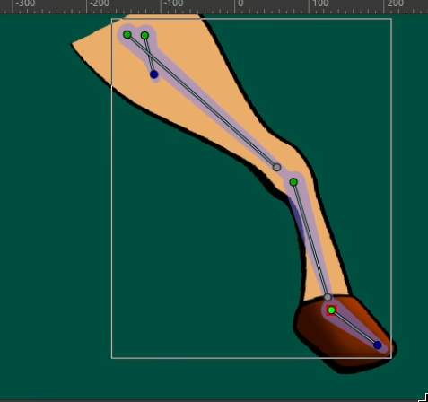
The Skeleton Deformation layer is used to deform images, BLine layers, and shapes, while the Skeleton layer is used to control valuenodes or individual points (such as BLine points).
Although FFD is similar to Skeleton Deformation, there is an important difference: in Skeleton Deformation, the mesh points/vertices (triangles) cannot be animated individually or manually bound to bones. As a result, the original mesh topology and structure remain fixed.
This makes it difficult to drive the deformation with controllers such as SmartBone, joystick, or slider plugins, and it also makes it difficult to animate individual mesh points independently.
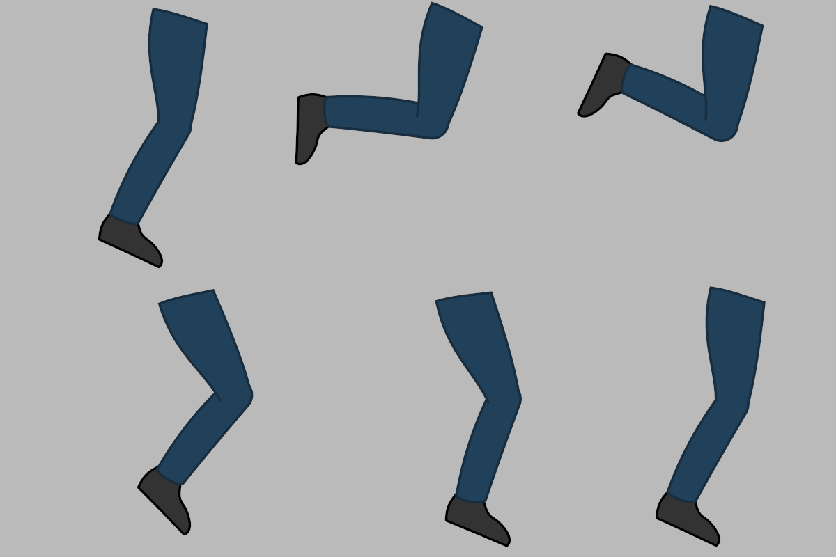
I was only comparing it with Skeleton Deformation. When I move the bones there, the image deforms smoothly without any visible cuts. However, with FFD—both the custom mesh and the grid mesh—I see parts of the image getting cut off, as if some areas are not being transformed.
I also noticed another issue: if I move the origin of the parent bone, the image sometimes disappears completely.


 .
.
 )
)