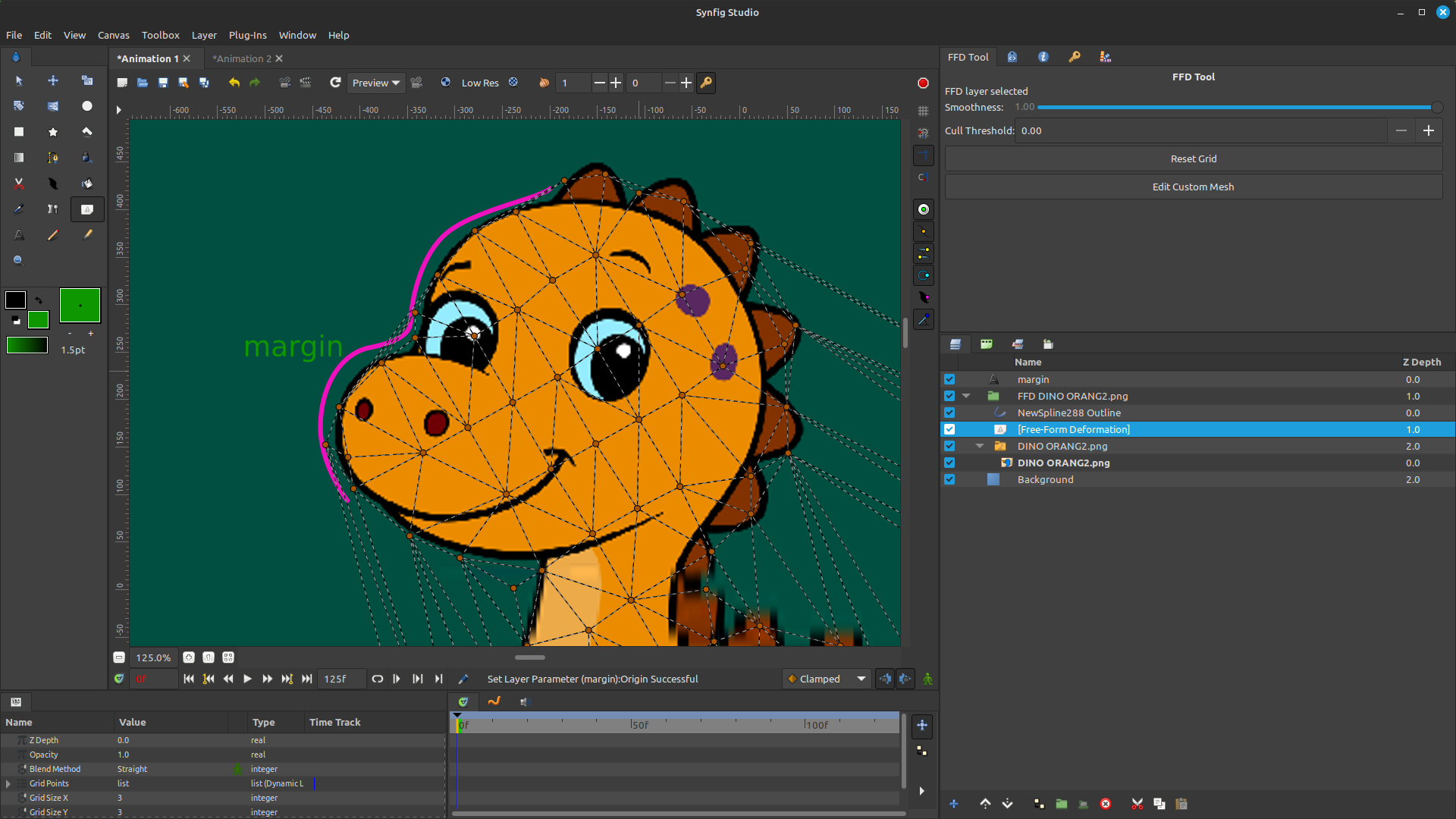
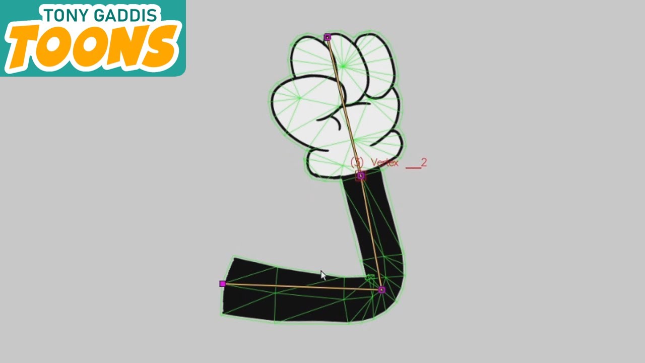
Now everything is working correctly the clipping behavior solved. I just want to mention a couple of notes regarding the Skeleton layer:
Option 1: Place the Skeleton Layer Above the FFD Layer
Simply drag the Skeleton layer above the FFD layer in the Layers panel.
Result: The FFD layer deforms the image first, and then the Skeleton layer is rendered on top, so the bones remain clean and are not distorted by the FFD.
Option 2: Group the Image and FFD Layers
If you prefer to keep your layers organized, place the Image layer and the FFD layer inside a Group Layer (Which is already automatically being done when creating ffd layer), then keep the Skeleton layer outside (above) the group.
Result: The image is deformed by the FFD inside the group, while the Skeleton layer is rendered afterward, ensuring the bones remain visible and undistorted.
For the custom mesh, it would be useful to have an adjustable margin option so users don’t have to edit the mesh again whenever they need extra coverage. A good example of this can be seen in OpenToonz:
I found a new issue: before the mesh is created, the points suddenly disappear when the user zooms the viewport.
I also tested it with a large image (larger than Full HD). My goal was to get more detailed deformation when bending it. However, I noticed that the image appears to lose pixel detail in the viewport. Fortunately, the final render still looks good, so it seems to be a viewport-only issue.
It’s not a major problem, but it might confuse some users in the future since the viewport quality doesn’t match the rendered result.
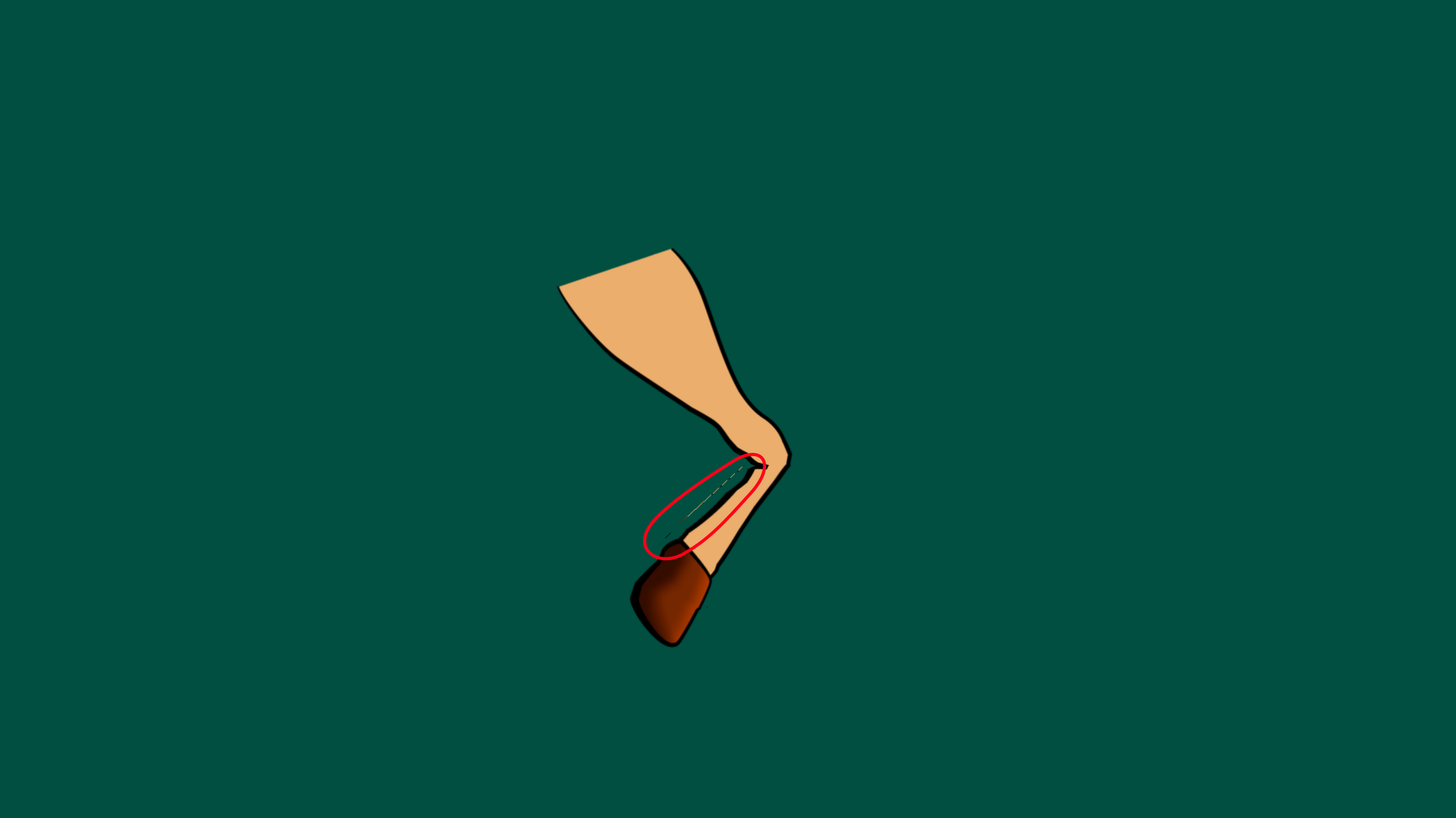
I also noticed some pixel leakage—there are thin lines of stray pixels appearing along the mesh.
The triangle edges disappear when the user sets the Cull Threshold to a value greater than zero. If I change it back to 0, the edges are displayed normally again.
A value of 0 means the feature is disabled. If you increase it to 1 for example, you’ll see the edges appear.
I can also change it from a numeric input to a slider to make it more intuitive and easier to visualize.
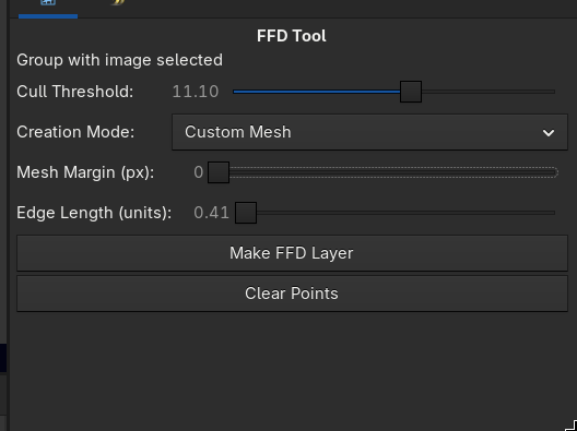
regarding to that video i removed the cull threshold parameters and implement a similar behavior to moho style so can u test it i think it is more suitable than the previous one.
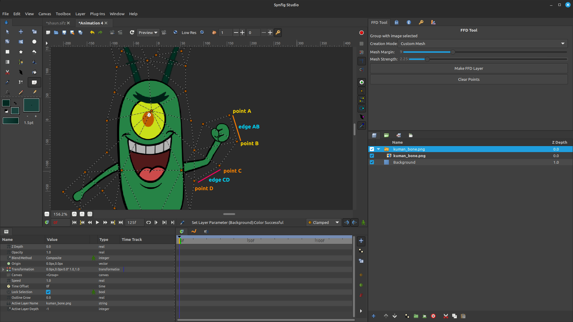
If the user collapses edge AB, point A can be removed because it is only connected to that edge. Point B should remain because it is still connected to two other edges. This part is already correct, but it looks like point B moves to a new position. I would expect point B to stay at its original position.
In the second case, if the user collapses edge CD, points C and D should both remain in their original positions, and only edge CD should be removed.
I think this behavior would be more intuitive and would preserve the existing mesh structure while minimizing unexpected changes to the remaining vertices.
Once the FFD has been created, I noticed that the edge guides are still visible. Shouldn’t they only be visible while editing or during the initial mesh creation.
Actually, I intended this behavior to apply only to FFD layers. I don’t see it as an issue. It could be useful for Splines as well, but what is the benefit of it in Splines?
there is something i forgot to mention but u can remove ducks using right click over the duck it self
In my opinion, it’s fine to leave it as it is. It’s not an issue that affects the Spline workflow. However, if other users or developers have concerns about it, they’re welcome to share their thoughts.
Sorry about that. I was testing different cases as I found them, but you’re right—I’ll update my previous messages instead to keep the discussion cleaner.
There is a problem with the imported image. The tool is trying to load the image from the original file path on your device instead of using the image embedded in the .sifz file.