I have a problem with animating some graphs. I have three overlayed graphs on the same sheet and I want circles to follow the curves of the graphs for presentation purposes. The x-axis is time while the y-axis shows various units depending on the corresponding curve.
To get each circle to follow the corresponding curve I have used a spline to trace each of the curves and linked each coloured circle to the corresponding spline which is easy.
The problem is that the curves are not the same shape so the circles move out of sync i.e. although the reach the end at the same time, they only time the are actually in line is at the beginning and end. I have been trying to link the circles with a reference “time circle” moving in the x-direction and using the spline to control the y-direction motion. Is this possible? So far I am getting nowhere…
Your best option is to try to make the splines “move” linearly on the x-axis.
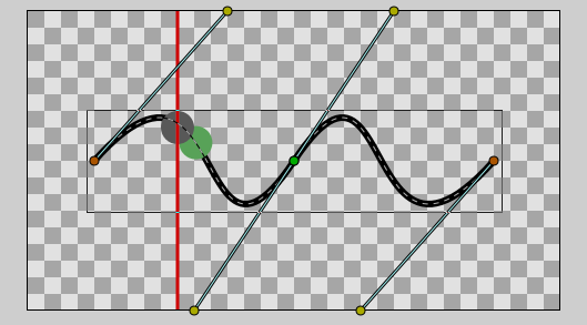
First make a perfectly straight spline along the x-axis. Place the tangents so that there’s three even spaces between the endpoint and tangents and between the tangents, like this:
(There’s 2 units space in between on this case).
Now when you link a circle to the spline and animate it from one end to the other it should move linearly. Remember to use linear interpolation. Also go to parameters panel for the linked circle, expand the Origin parameter node and turn off Homogeneous.
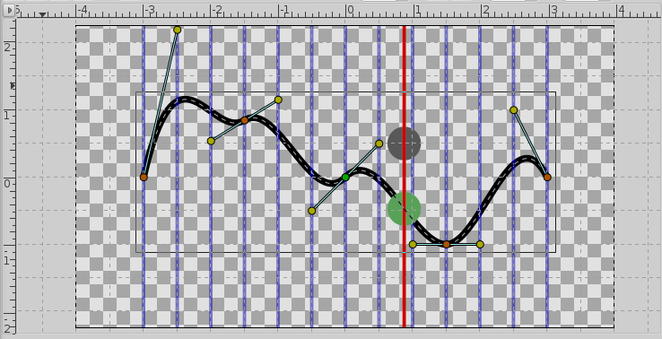
This motion will remain linear along the x-axis as long as you keep the horizontal spacing of the vertexes and tangents the same. You are free to move the tangents and vertexes in the y-axis direction all you want. Hold Shift key or use Snap to Grid feature to make restrict motion along the y-axis. The results:
You will probably want to add more spline segments to be able to reproduce the shapes of the graphs, just remember to keep the horizontal spacings uniform.
Sorry to get into your (often very good) advices … but… i think that it doen’st work has expected (or i missed a point? … i have tried with several combination of the Homogeneous spllne & circle-linked param) constant-x-speed-vertex-added.sifz (1.44 KB)
The reason this works is because of the properties of bezier splines. When the control points are evenly (tangents = control points) spaced the spline reduces to linear interpolation between endpoints. And since the X and Y coordinates are calculated independently, the spline can be linear along just one direction.