i was struggled while drawing a fan-art that has so many outlines from different layers,
and it was totally confusing since i have to trace them back by outlines
so i decided to check some solutions of how to fill Outlines at tutorial sections…
and some most reliable solutions are the “Export value one-by-one” and “link one-by-one” method which i’m not really liking to do
then i tinkered Synfig around and end up with this…
it’s not the most convenient one since it was pretty confusing, but it’s quicker and no exporting required.
plus, it works almost like the “Export Value” ones so that’s much better for me
EDIT: Be aware though that this method will disable the spline point’s ability to be animated (see 2nd post below)!!!
I’ll just try to explain what i did here in case someone want to know
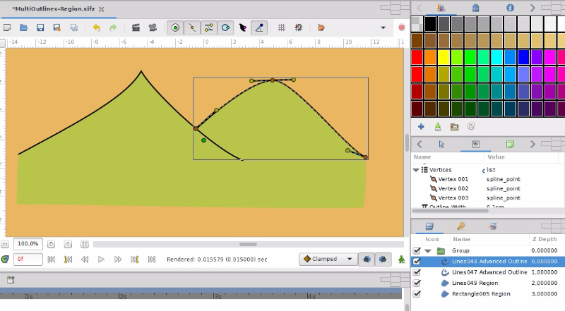
Draw both Advanced Outline and Region separately
Disconnect a spline point from both layers
Then select Vertex Points from both layer then right click and “Link”
Now it should link in and follow the region or advanced outline vertex and its tangent’s settings (split/merge)
Note that it uses Link Tier 5 Law, so nudge a point from layer that you want to move when linking them first
it also disables the ability to split/merge tangents
To do that you need to convert the outline (or region, it’s up to you) back to composite so you can change them again, then disconnect it again and link them back
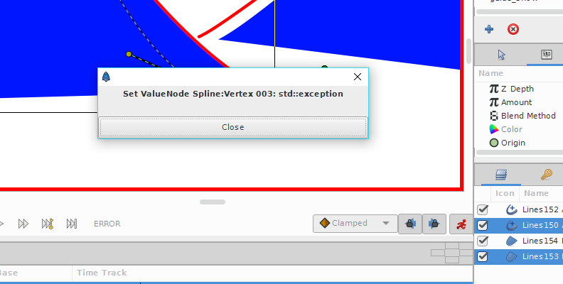
so it turns out there’s a new founding in this method, and it’s totally not nice
the spline disconnecting actually disables the spline point’s ability to be animated. In fact, we can’t animate this point, unless it got converted back to any type of course.
That’s as far as i could tell, still couldn’t figure out the solution yet…
Well, it surely is a pity that there’s no way to link path vertices directly, but there’s a workaround: link origin and tangents separately. You’ll still have to handle “split tangents” manually, though.
Recommended workflow:
Create the whole shape
Create outline from region (you can skip this if you created outlines originally)
Disconnect outline’s vertices
Remove unneeded vertices from it (note that unlooping at this step will make it impossible to link ending tangents, so if you need that don’t unloop yet)
Select both outline and region layers
For each vertex origin and tangent that you need to link: draw rectangular selection around it (this selects them on both layers) and link
Unloop outline path if needed
Done. You can repeat from second step to make more outlines
Yeah, it’s animateable. The reason your approach makes animating impossible is that you convert path vertices into type that isn’t recognizable to synfig’s animated value node/waypoint system. Since i leave them in default “composite” value node type, you can still animate them just like any other linked values.
Note that to actually make this useful, you’ll need some unlinked vertices in outline and to create them might (in case you linked all vertices already) need to temporarily set looping on, insert item, unloop and “rotate order” if necessary. test-47-split-spline-no-export.sif (18.3 KB)
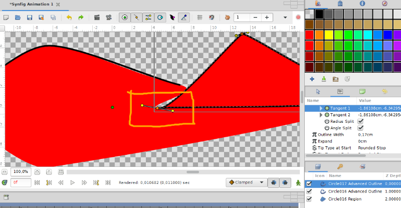
The one that i marked on got both spline’s tangents split-up, but still act like a stiff tangents, keep themselves merged…
the other one totally got inverted, probably lacking of “Rotate order”…
also,should i just draw the outlines from shape tool, to make sure the outlines linked properly…?
also one unnecessary question, :
is there any differences when disconnecting outline’s vertices and region’s…?
No idea why that happens. Try uploading that file if the issue will still be present.
Anyway, i just noticed that you have inner vertex in region layer in your first example as well. I suppose its advantage is that all vertices are linked, but on the flip side you have to deal with the shape being more complex than it needs to be (and i suppose it can get tricky if animated). Anyway, if you do that anyway, you can try even simpler approach (though it has its downsides too): instead of unlinking and manual partial linking use width points to cut unneeded pieces of outline.
Rotate order only rotates - it doesn’t really change order (e.g. 123->231->312, but you’ll never get 321). Unfortunately there doesn’t seem to be a way to reverse order.
You can add more full outlines by right-clicking on region layer → make outline/advanced outline. Then unlink and remove unneeded vertices. This should make it quick (you don’t have to trace existing shape by hand and they will be in perfect position to link later) and will ensure proper order.
The only difference i can think of is that you’ll get different UIDs (if any at all) inside save file, which shouldn’t really concern you.
TestLineLink.sifz (4.97 KB)
but What if the scenario is different…?
I almost finished my lineart of a drawing and i want to fill them, is this method still possible…?
Yup, already know that
But probably not very practical because sometimes i moved the linearts around, and their width points got moved away a little bit so i need to readjust them again
Hmm, this is really weird. Even after disconnecting this vertex, region one was still acting as though its tangents are linked, ignoring split tangents setting. Only “disconnecting” one of the tangents (and then converting it back to “composite”) helped. Might be some kind of bug.
If your lineart consists of many outlines, you won’t be able to auto-convert them into one region (unless you don’t mind editing .sif in text editor - it should be pretty easy there). Manually linking should work though (as long as you pay attention to drawing order).
Yeah, that’s the main downside. Though as long as you place width points exactly on top of outline vertices, it shouldn’t move anywhere (make sure “homogeneous” parameter is disabled). There is in fact a hacky way to ensure exactness: open width point in parameters dock, set its “upper bound” to amount of vertices in outline and set “position” to number of vertex it should be on top of (numeration starts from 0). MultiOutlines-Region-animated.sifz (2.52 KB)
yeah, that’s what i thought so…
Maybe because the linking settings got piled up somehow…
Well i don’t mind if that’s the only way, it’s just pretty tedious. But as long as i remember the Linking Tier 5 law (and fiddle the region abit first), and not mess up the whole lineart that’s pretty fine
I do curious how the editing works like, but even looking codes from a simple mountain drawing is more than enough to make me dizzy, so… i don’t know if that’s a good idea
but i am really, really curious so some explanations are needed
Wow, i didn’t know that is possible !!
This hack surely gonna be very useful, Thanks!
Since there’s not much of solutions (other than some that got listed above and the ones from the tutorial page), i’ll put the [SOLVED] in for now
at least until there’s an awesome synfig update that will allow this glorious thing…
Once again i really thank you very much for the assistance!!
Well, first you need to make sure you use editor with decent XML support (with at least highlighting, element folding and auto-indentation features) and basic understanding of how XML works (pretty much as HTML so if you know it, that’s enough as well). For layer editing (which is the only thing you’ll really need unless you use exported values or bones) you can imagine .sif as mostly reflecting layer hierarchy (though inverted - top layers are last in the file) and parameters hierarchy inside layer (parameters dock could be seen as a simple specialized XML editor :D).
For basic things like deleting layer you just search for its name (if it’s unique - if it’s not, you’ll have to distinguish by its type or contents or position in layer tree…) and do something with it. In case of deleting - just select everything from ‘<layer … desc=“LayerName”>’ to the appropriate (in case of simple, non-group layers it will be nearest ) and delete it. To tweak some parameter, you just find it and edit.
As for dealing with curve paths (called splines in synfig interface, but blines in .sifs), if you understand how they work in Synfig, you should be able to translate that knowledge to .sif. In order to combine several splines into one by simply reusing all its knots, you just need to copy those knots. So, find first layer, then find its “bline” param (). There will be <bline …> element inside and inside that are many s. Simply copy those entries and paste them into end (or beginning) of target bline.
In fact, i didn’t know about it either. But knowing bezier curves i figured it should work like that. Note that you can get away without setting “upper bound” - it is there only for convenience - you can set “position” to M/N value instead (where M is target vertex number and N is total number of them in given spline). Also note that you’ll have to do this again if you change amount of knots in spline.
Hi, a bit of discovery to share here, it’s quite good
so, the workaround that you gave here,
it’s actually possible to add more lines and extend the region layer, and it end up just like that
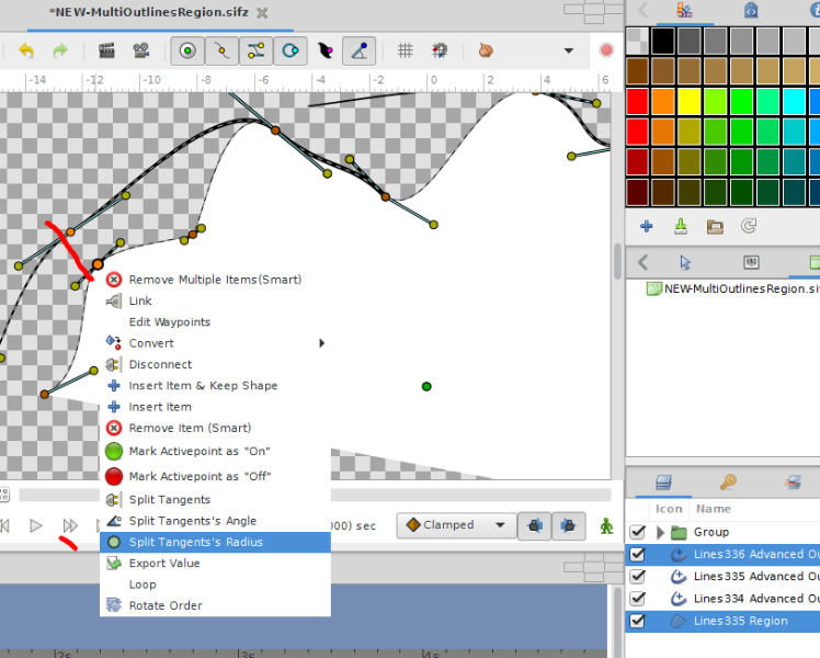
after inspecting the workaround, along the circle tool that used there, i realize that to make the similar kind of link all i need to do is to set the region’s spline tangents radius to split (and keep their angles merged)
next, link them to outline’s vertex and tangents, then i can safely fiddle with outline’s tangents and it’s still easy to fix if both doesn’t look right
just make sure that before linking, the tangent’s setting is only “Radius Split”, not “Angle Split” or even both
to extend them safely simply dupe that outline, disconnect from vertices list and arrange it, add items in region layer, rinse and repeat
now, it’s not 100% working all the time, in a small of occurrence a bit of repeating is needed
but it works to me for most of the time so i might as well use it
also if you split a region’s spline tangents then link them to outline’s vertex and tangent’s,
and then do some split and merge tangents, that bug gets triggered (that Stuck-like-a-Knot bug)