Part I: Artist guide
What FFD does
Free-Form Deformation warps bitmap artwork by mapping an undeformed source mesh to a moved destination mesh. The artwork follows the control points without the artist having to redraw it.
FFD offers two mesh types:
-
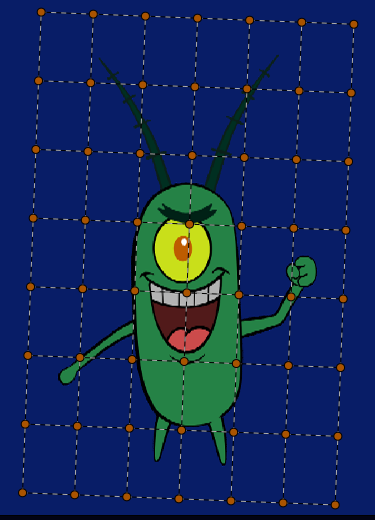
Grid is a regular rectangular lattice. Use it for broad bending, stretching, squash-and-stretch, and smooth character motion.
-
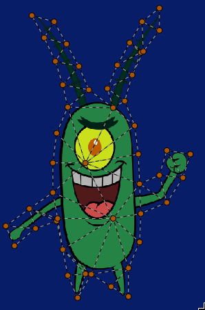
Custom Mesh is a triangle mesh fitted to the visible image. Use it when an irregular shape needs focused control without a large rectangular grid.
The FFD layer performs the deformation. The FFD Tool creates and edits the mesh structure. Selecting an FFD layer does not switch tools automatically; choose the FFD Tool explicitly when structural editing is needed.
Artist phase 1: Prepare the artwork
-
Put the bitmap artwork inside a Group or Switch Group(It is already created when you import any image).
-
Select that Group or Switch Group in the Layers panel.
-
Select the FFD Tool.
The selected group must contain at least one image layer, including images in nested groups. FFD cannot be applied directly around an external imported canvas. Open the imported file in its own tab and apply FFD to a group there.
Artist phase 2: Create a Grid mesh
-
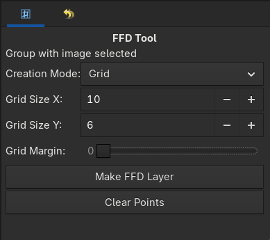
Set Creation Mode to Grid.
-
Set Grid Size X and Grid Size Y. These are control-point counts, not cell counts. A 3 x 3 grid contains nine points and four cells.
-
Increase Grid Margin if the preview is too close to the artwork.
-
Click Make FFD Layer.
The preview examines visible alpha, estimates the artwork’s orientation, and fits a rotated rectangle around it. Synfig distributes the requested control points across that rectangle.
Use fewer points for large, clean bends. Add points only when the artwork needs more local control; every point increases editing and animation work.
Artist phase 3: Create a Custom Mesh
-
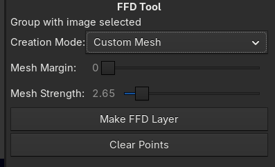
Set Creation Mode to Custom Mesh.
-
Adjust Mesh Margin. This expands the detected image silhouette before points are generated.
-
Adjust Mesh Strength. Higher values create more boundary and interior points; lower values create a simpler mesh.
-
Inspect the preview triangles.
-
Left-click to add a point, right-click a point to remove it, or use Clear Points to start again.
-
Click Make FFD Layer.
At least three points are required. Transparent pixels do not contribute to the detected silhouette. A clean alpha channel generally produces a cleaner automatic mesh.
After either creation mode, Synfig:
- Creates a parent group named from the selected group.
- Moves the selected artwork group into it.
- Adds a Free-Form Deformation layer above the artwork.
- Transfers the selected group’s origin and transformation to the new parent so its visual placement is preserved.
- Selects the new FFD layer and returns to the Transform Tool.
Artist phase 4: Deform and animate
- Select the FFD layer.
- Use the Transform Tool to drag its control points.
- Enable animation mode and move points at different times to animate them.
The visible lines are an editing overlay. In Grid mode they show rows and columns; in Custom Mesh mode they show triangle edges. The points are stored in an animatable dynamic list, so each point can receive waypoints.
Linking to Bones
FFD meshes can be driven by a Skeleton layer, which is useful for character rigging:
1. Create a Skeleton Layer and build your bone structure.
2. In the Layers panel, select both the Skeleton Layer and the FFD Layer (hold `Ctrl` to select multiple).
3. In the canvas, click on a bone to select it.
4. Select the FFD control points you want to attach to that bone (drag a selection box or hold `Ctrl` to click individual points).
5. Right-click one of the selected FFD points and choose Link to Bone.
The linked points will now follow the bone’s translation, rotation, and scale. You can link different sections of the FFD mesh to different bones to deform a continuous image across joints.
Artist phase 5: Change the mesh structure
Select the FFD layer and then choose the FFD Tool.
Grid editing
- Click Edit Grid.
- Change the row or column count.
- Click Update Grid.
Synfig samples the existing deformation into the new grid instead of resetting it. The result remains close to the previous shape, although changing topology cannot preserve every detail exactly.
Custom Mesh editing
- Click Edit Custom Mesh.
- Add, remove, or move points.
- Right-click an edge for topology operations.
- Click Update FFD Mesh to persist the point and triangle lists.
Updating a Custom Mesh replaces its source points and current control points with the edited structure. This resets the current deformation, so finish structural editing before building detailed point animation where possible.
Edge operations:
- Split Edge inserts a point at the clicked position and divides every triangle sharing that edge into two.
- Swap Edge replaces the shared diagonal between exactly two adjacent triangles with the opposite diagonal.
- Collapse Edge moves the retained endpoint to the midpoint, merges both endpoints, removes degenerate triangles, and renumbers later point indices.
- Subdivide Adjacent Triangles adds a centroid to each triangle touching the selected edge and replaces that triangle with three triangles.
Editing shortcuts:
| Input |
Effect |
| Left-click empty space |
Add a point |
| Right-click a point |
Remove that point |
Delete or Backspace |
Remove the last point |
Ctrl+Z |
Remove the last point in the tool-local point history |
Ctrl+Y |
Restore the last removed point |
Artist phase 6: Reset and troubleshoot
- Reset Grid recreates the undeformed grid from its saved source rectangle and angle.
- Reset Mesh copies the saved Custom Mesh source points back to the current control points.
- Resetting removes deformation but does not delete the FFD layer.
Common problems:
| Problem |
Cause or action |
| No creation controls |
Select a Group or Switch Group containing an image |
| Auto Mesh finds too few points |
Adjust Mesh Margin or Mesh Strength and ensure the image has visible alpha |
| Mesh has too many points |
Lower Mesh Strength |
| Imported canvas is rejected |
Open it in a separate tab and apply FFD internally |
| Selecting FFD does not open its tool |
This is intentional; explicitly choose FFD Tool |