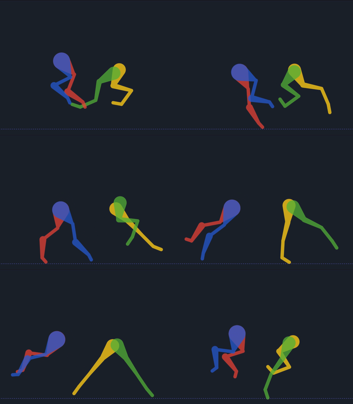
Not a rig as such, but a little test animation for the IK converter.. Rigid skeleton.. Hind end worked perfectly, and I’d say 90% correct for the front legs. A flip has to be introduced to mimic the scapula to elbow movement of the horse. Elbow to radius on the front legs at the back of the movement is not easily solvable, but most would not notice unless you’re a bio equine mechanic (yes that an actual job, and worked with one for 2 years in motion capture for a few feature films)
Thanks for the explanation.
The front legs of a horse are definitely much more complex than the hind legs because the scapula motion heavily affects the elbow and radius movement. At the moment, the IK angle setup I made is mainly focused on keeping the main bone chain stable, so the scapula behavior is not fully simulated yet.
I agree that some kind of flip/pole system will probably be needed to better mimic the scapula-to-elbow transition, especially during the backward phase of the stride. For now, I may leave the two distal joints partially manual or add a dedicated mode for animal front legs.
It’s also very interesting to hear about your experience working with equine biomechanics and motion capture for films — feedback like this is extremely valuable for understanding more realistic rig behavior.
I just tested your IK bones functions. Just from looking at the example files ik_2JOINTBONE.sifz and ik_3JOINTBONE.sifz , I am very impressed at what we can do with it.
I have 2 immediate questions:
I can only move the hip joint and the tip of the foot.
Correction: when I select the skeleton, I can’t move the ankle. But when I select something else, the true handle (duck?) appears and I can move the ankle and foot.
Where can I change the length of the bones, so I can apply it with my character?
If I want to have 4 of these IK functions, should I copy paste into a new document? (or copy-paste with exported value renaming in between?)
Yes,The hip joint and the tip of the foot are the main controls. The other bones are driven automatically by the IK system.
To avoid overlapping handles, you can disable Toggle Vertex when using Toggle Position.
You can also adjust the duck handle offset in duckmatic.cpp to move the toggle ducks farther away from their original positions. There is a small trade-off with this approach, but I find it much more comfortable to work with.
Another option is to create separate controller bones for the target and the shoulder. Then link the target origin and shoulder origin to those controller bones. This way, when you want to move the leg (the target), you only need to manipulate the controller bone layer instead of the original rig.
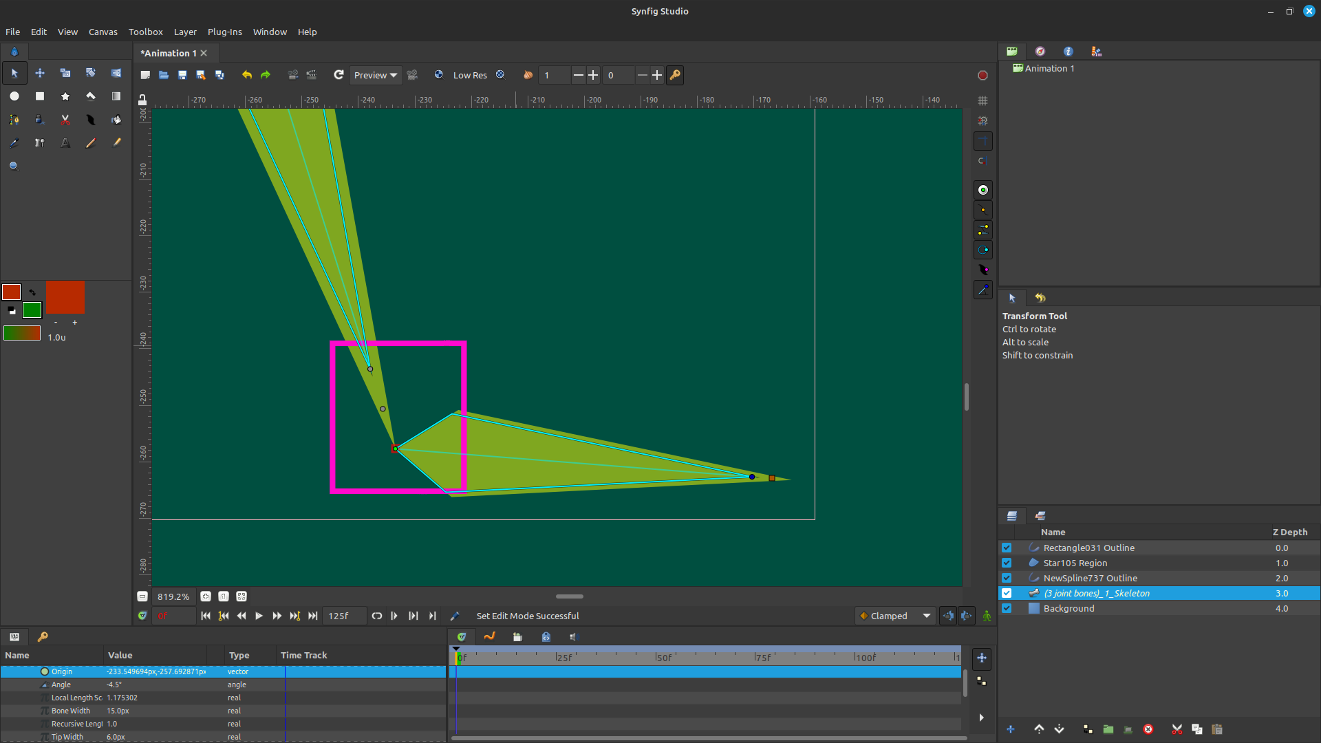
You can see that the bone length duck is positioned between the angle and position ducks. This helps prevent the duck handles from overlapping, making them easier to select and manipulate.
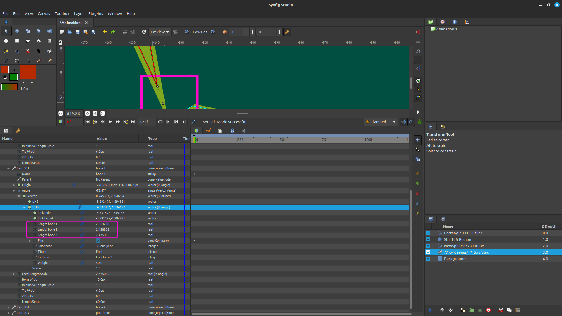
To change the IK bone lengths, look for the ValueNode that contains the IK Angle converter. There you’ll find the parameters Bone Length 1, Bone Length 2, Bone Length 3, and so on. You can change those values manually to whatever you need.
With just a few converters, you can change the bone length directly on the canvas. You can use the Add and Subtract converters for this. You can see an example in this file.
At the moment, this is a manual workflow. There are other ways to expose it through the UI, but for now, editing the values directly is the easiest approach.
Since these values are linked, changing one will automatically update the corresponding bone lengths throughout the rig. Just be careful not to disconnect those links, as doing so will affect the behavior of the other bones.
Yes, of course—you can simply duplicate the layer.
You can also use the Insert Template – IK Angle plugin. It already includes several ready-to-use rigs, such as a human rig, a dinosaur rig, and other animal rigs. More templates may be added in the future. You can also study how it works by looking at the rig.
There’s also a plugin that converts a regular bone setup into an IK Angle rig automatically, so you don’t have to manually edit the bone lengths afterward.
insert template IK angle:
convert to IK angle:
for bone target set code by converter ‘grey’ . for bone shoulder(pole) set with converter ‘converse’
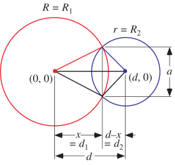
The basic idea behind my IK Angle converter is based on the geometric intersection of two circles.
Imagine a simple two-bone chain. The first circle is centered at the root bone with a radius equal to the length of the first bone. The second circle is centered at the target with a radius equal to the length of the second bone.
The intersection of these two circles gives the possible position of the intermediate joint (for example, the elbow or the knee). Once that joint position is known, the rotation angle of each bone can be calculated directly using vector angles.
Because this approach is based on geometry rather than an iterative solver, it produces a stable solution with very little computation. There is no need for repeated iterations such as those used by CCD or FABRIK for a simple two-bone chain.
To support different bending directions, the solver simply chooses one of the two possible intersection points (for example, left/right or up/down), depending on the desired pole direction.
This geometric approach is the core idea behind my IK Angle converter.